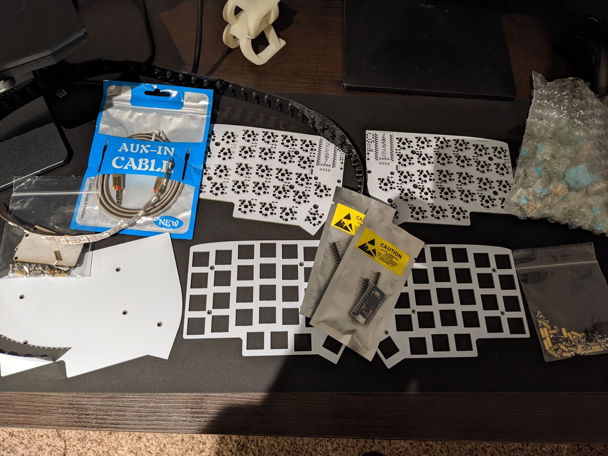
- Lily58 PCB
- Mirco usb cable
- AUX cable
- 58 switches (I went with Zilent 62g tactiles)
- Key caps
- Plates
- Hotswap sockets
- 58 SMD diodes
- 2 Microcontrollers (or nice!nanos if you're going wireless)
Tools needed:
- Soldering Iron
- Solder
Before soldering, I would make a mental note or add a piece of tape to distinguish which side is which. This is to prevent soldering the same side twice.
Soldering Diodes
Solder the diode wire pointing in the direction of the arrow symbol on the board like so: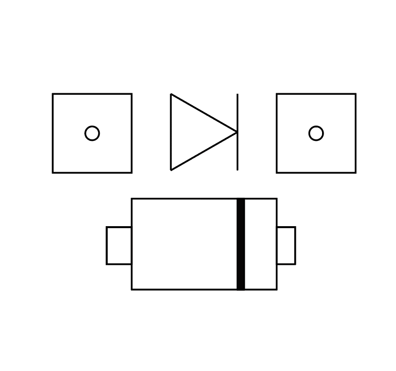
I would start by applying solder on one pad of every diode
Then with tweezers solder one side of the diode, using the side that has the solder to make it easier to secure. Afterwards, solder the other side of the diode.

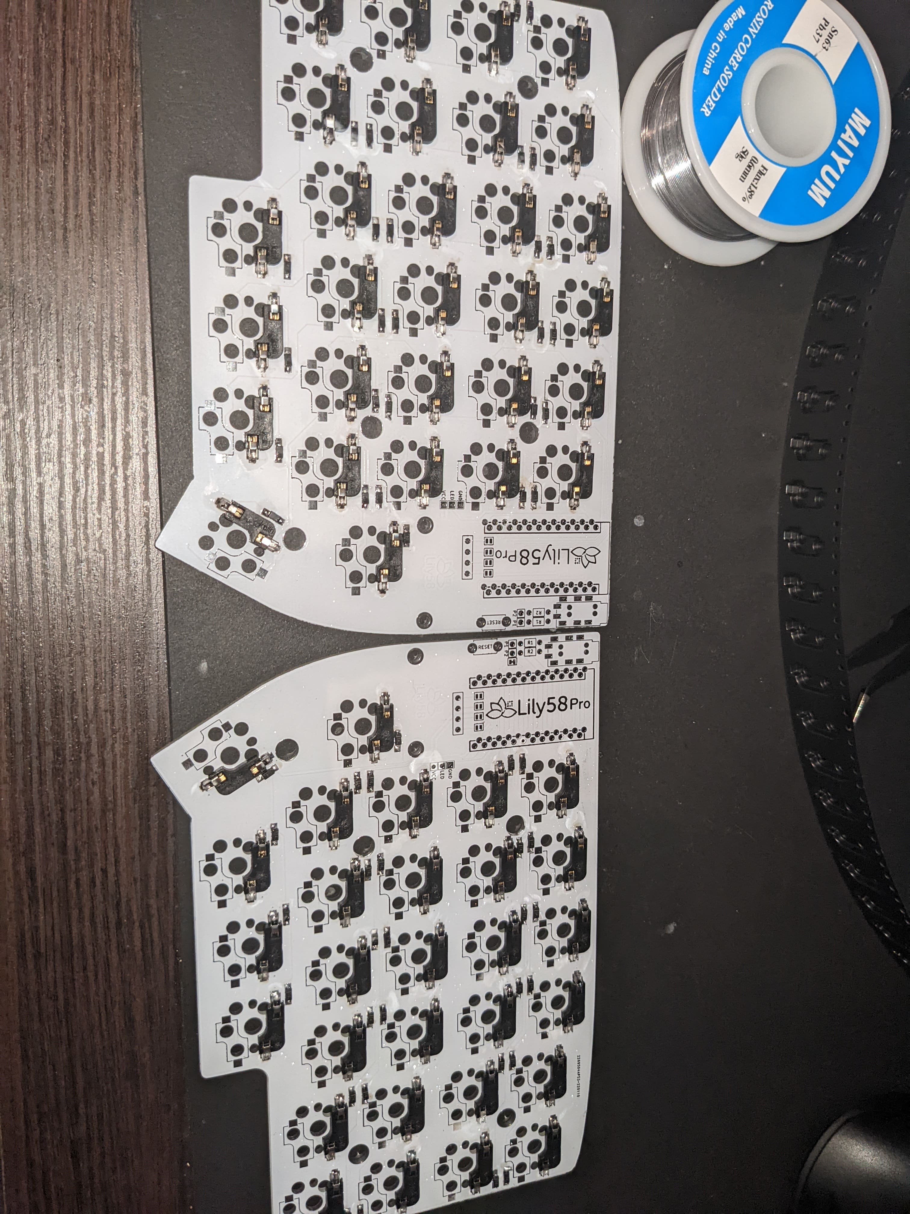
Soldering the sockets
You want to solder the sockets on the same side as the diodes. I did the same approach with the sockets as the diodes. I added solder on one side and then placed the socket.
Soldering Audio jack and reset switch
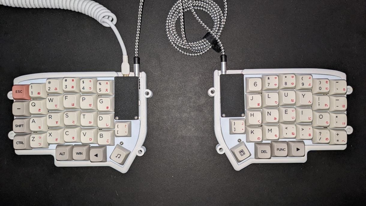
The audio jack and reset switch are soldered on the opposite side of the board. The side they're on is supposed to be the top part of the board, with the diodes and sockets being the bottom side. For both components you have to turn the board over to solder the pins. The aux ports should be on the right for both sides.
Installing the Pro Micro
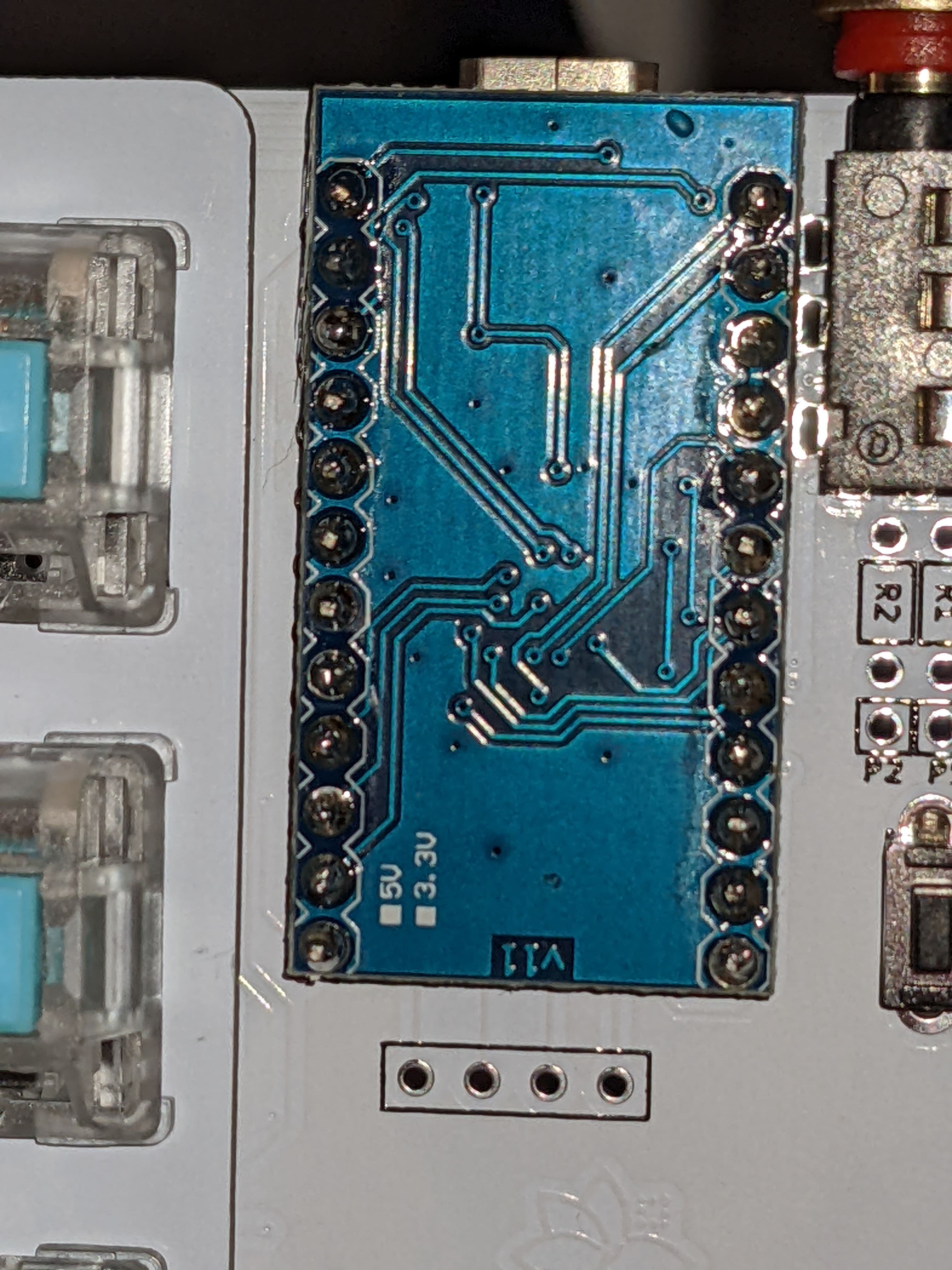
The Pro Micro is personally the thing that gave me the most trouble. I had to buy a few replacements because I didn't properly solder them and ruined them because of how fragile they are added with my inexperience with soldering electronics.I started by connecting the pins to a breadboard to hold the pins securely, but this is completely optional. I then soldered the pins to the microcontroller, you need to insert the microcontroller on the short side of the header pins, and then you solder every pin. The microcontroller should also be upside down (the micro USB port should be on the bottom)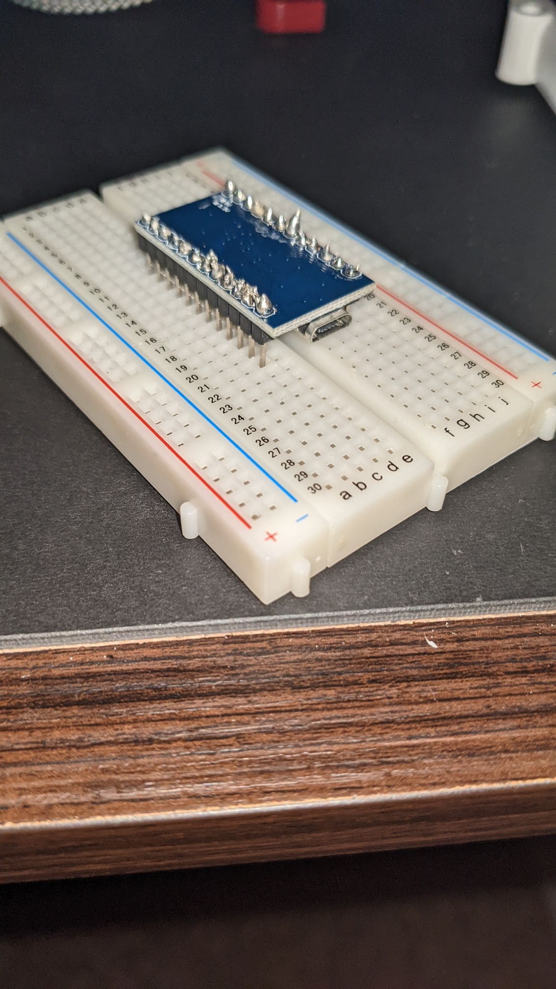
Adding the switches
Now that the hard part was out of the way, it was time to add the switches. I inserted one switch in the 4 corners of the top plate in order to secure the position of the plate, and then I filled the rest of the board. Afterwards, I added the key caps and screwed the case onto the PCB.Adding the Firmware
Now that I had everything installed on the PCB, it was time to add the firmware to the keyboard. I used the QMK tool on Linux to install the key map. I did this for both sides separately, using the commanddoas make lily58:custom:avrdude in the qmk_firmware directory. Once it said Detecting USB port, reset your controller now ... I clicked on the reset switch on the board to write the key map. I used a custom key map because I use the Colemak keyboard layout and I also moved some things around. You can do this by going into the qmk_firmware/keyboards/lily58/keymaps/default directory and changing the keymap.c file. I followed this guide to figure out what key codes worked, and then I just used the original command to write to the board. However, if you don't plan to add any special modifications to the key map, you can just use doas make lily58:default:avrdude to install the default QWERTY key map and go from there.Final Steps
After the firmware has been written, you can connect the two PCBs together and connect the micro USB cable to the computer. Everything should've worked, but I had a few issues. A few keys didn't respond, and the issues were that I soldered the sockets wrong, so I had to either add more solder to the joint, or I had to replace the socket because I had damaged it. For one key, I soldered the diode in the wrong direction so I had to desolder it, turn it around, and resolder it for it to work. Building the keyboard took me around 4 hours to build.